Let’s discuss the question: how to read gd&t feature control frame. We summarize all relevant answers in section Q&A of website Bmxracingthailand.com in category: Blog technology. See more related questions in the comments below.

How do you read a GD&T drawing?
If the arrow points to a diametric dimension, then the axis is controlled by GD&T. If the arrow points to a surface, then the surface is controlled by GD&T. The arrow is optional and may not be present on some drawings. This is where geometric control is specified.
What is basics of Gd?
The language of GD&T consists of dimensions, tolerances, symbols, definitions, rules, and conventions that can be used to precisely communicate the functional requirements for the location, orientation, size, and form of each feature of the design model.
Reading GD\u0026T Drawings Step by Step
Images related to the topicReading GD\u0026T Drawings Step by Step
How do you read position tolerance?
An example of position tolerance is shown below. The top figure shows the position symbol applied to two holes. The boxed symbols can be read “relative to datums A, B, and C, the position of these hole centers shall lie within a cylindrical tolerance zone of diameter 0.3″.
What does Cylindricity mean?
Cylindricity specifies the roundness and straightness of a form. When measuring cylindricity, you are checking for distortion in the cylinder, to verify the accuracy of its cylindrical form.
What are the 3 types of tolerances?
These are grouped into form tolerance, orientation tolerance, location tolerance, and run-out tolerance, which can be used to indicate all shapes.
What are the 5 categories of symbols used in GD&T?
There are fourteen geometric characteristic symbols used in the language of GD&T. They are divided in to five categories namely form, orientation, location, runout, and profile.
What does flatness mean in GD&T?
Flatness is a measure of a surface’s form compared against itself, indicating that all the points along the surface lie in the same plane. Symbolized in GD&T by a parallelogram, flatness allows you to limit waviness or variation in a surface without tightening its dimensional tolerance.
How do you measure profile of a surface?
Profile is usually measured using a CMM due to the complexity of some of the surfaces that are called out. The CMM would compare the 3D scan of the profile to the dimensions called out on the drawing to see if it was in spec.
How do you manually check true position?
True position is the deviation between the theoretical position on a drawing and the actual position, measured as the centerline, on the final product. True position can be calculated using the following formula: true position = 2 x (dx^2 + dy^2)^1/2.
Why do you multiply true position by 2?
You then mutilply this number by TWO to get the DIAMETER TOLERANCE ZONE of the actual offset of the measured hole feature. Hope this helps!
Does true position need a datum?
True position of a feature is made by first determining the current referenced point and then comparing that to any datum surfaces to determine how far off this true center the feature is. It is simplified like a dimensional tolerance but can be applied to a diameter tolerance zone instead of simple X-Y coordinates.
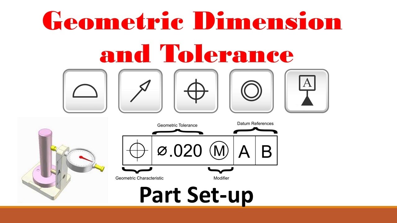
#GD\u0026T (Part 1: Basic Set-up Procedure)
Images related to the topic#GD\u0026T (Part 1: Basic Set-up Procedure)
What is the best way to verify circularity?
Gauging / Measurement:
Circularity is measured by constraining a part, rotating it around the central axis while a height gauge records the variation of the surface. The height gauge must have total variation less than the tolerance amount.
What is MMC and LMC?
MMC is the condition of a feature which contains the maximum amount of material, that is, the smallest hole or largest pin, within the stated limits of size. LMC is the condition in which there is the least amount of material, the largest hole or smallest pin, within the stated limits of size.
How do you assign datums?
We can place the datum symbol either on the surface or on one extension line from the surface. For any surface other than a round cylinder, the datum is strictly on the side where the symbol is shown. However, for a round cylinder, the datum is the entire round surface.
What does flatness symbolize?
Flatness. GD&T Flatness is a common symbol that references how flat a surface is regardless of any other datum’s or features. It comes in useful if a feature is to be defined on a drawing that needs to be uniformly flat without tightening any other dimensions on the drawing.
How do you calculate angularity?
Gauging / Measurement:
Angularity is measured by constraining a part, usually with a sine bar, tilted to the reference angle, so that the reference surface is now parallel to the granite slab. By setting the part at an angle the flatness can now be measured across the now horizontal reference surface.
What is profile of a line?
Description: Profile of a line describes a tolerance zone around any line in any feature, usually of a curved shape. Profile of a line is a 2-Dimensional tolerance range that can be applied to any linear tolerance.
What is the meaning of H7?
International Tolerance grades
They are labelled with a letter (capitals for holes and lowercase for shafts) and a number. For example: H7 (hole, tapped hole, or nut) and h7 (shaft or bolt). H7/h6 is a very common standard tolerance which gives a tight fit.
What is size limit?
Limits of Size:
The term limits of size referred to the two extreme permissible sizes for a dimension of a part, between which the actual size should lie. The largest permissible size for a dimension is called upper or high or maximum limit, whereas the smallest size is called lower or minimum limit.
How do you calculate tolerance?
TOLERANCE – Usually provide as a percentage of the expected value. It can be plus or minus. Tolerance = (Measured Value – Expected Value)/Expected Value. In the above case the Tolerance is (75.1-75.0) / 75 = 0.13%.
How many GD and T symbols are there?
Geometric tolerances are specified using symbols on a drawing. Currently, we have 16 symbols for geometric tolerances, which are categorized according to the tolerance they specify.
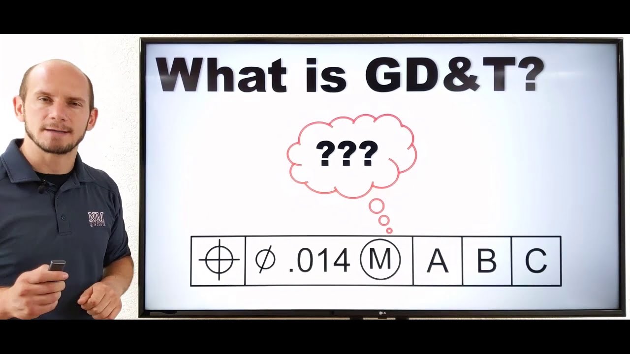
What is GD\u0026T in 10 Minutes
Images related to the topicWhat is GD\u0026T in 10 Minutes
What true position means?
True position is a GD&T callout for specifying the position of a feature. It is more correctly referred to as “position”. We use this concept in GD&T to control the variation of a specific feature from its desired position. This is important for mating parts to ensure a seamless assembly.
What is dimensional tolerancing?
Dimensional tolerances are a crucial part of the design and manufacturing process. A tolerance is a numerical range of measurements assigned to a part’s dimensions indicating how much a manufacturing team can drift from the nominal measurement.
Related searches
- how to read gds file
- how to read gd&t pdf
- real gdp
- geometric dimensioning and tolerancing
- gd and t symbols
- how to read gdp numbers
- how to read gdp growth rate
- how to read gd&t drawings
- how to read gdp chart
- how to read gd&t true position
- what does gd gd mean
- gd=detect means in graphics
- how to read feature control frame
- how to read gd&t
- gd&t
- how to read unilateral tolerance gd&t
- feature control frame symbols
- how to read gdp data
- how to read ged files
- feature control frame
- gd and t pdf
- how to read gdb backtrace
- tips for gd
- how to read gdb output
- a feature control frame must be connected to
Information related to the topic how to read gd&t feature control frame
Here are the search results of the thread how to read gd&t feature control frame from Bing. You can read more if you want.
You have just come across an article on the topic how to read gd&t feature control frame. If you found this article useful, please share it. Thank you very much.