Let’s discuss the question: how to make half wave rectifier circuit on breadboard. We summarize all relevant answers in section Q&A of website Bmxracingthailand.com in category: Blog technology. See more related questions in the comments below.

How do you make a half wave rectifier circuit?
To build a half wave rectifier circuit, the only electronic components that you need are a diode and a resistor. The diode can be any rectifier diode such as a 1N400X diode and any resistor in the 470Ω range.
How does a half wave rectifier circuit work?
Working of Half Wave Rectifier
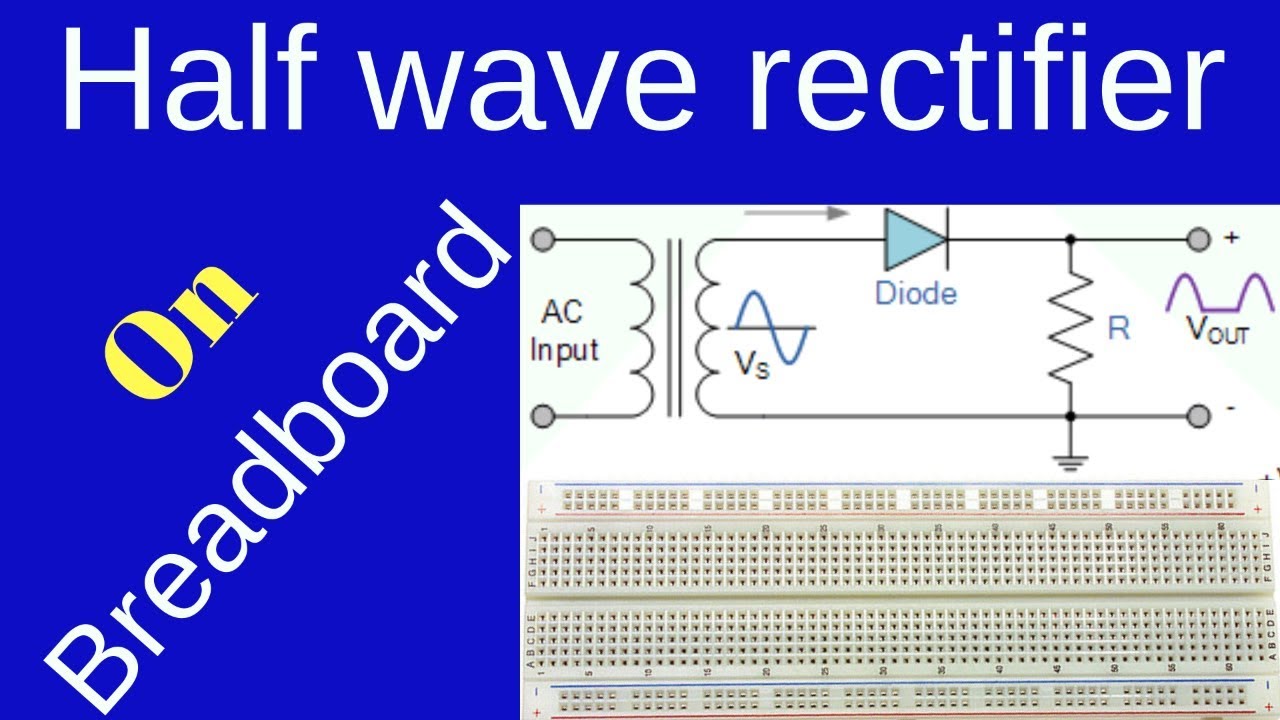
A high AC voltage is applied to the primary side of the step-down transformer. The obtained secondary low voltage is applied to the diode. The diode is forward biased during the positive half cycle of the AC voltage and reverse biased during the negative half cycle.
How to make half wave rectifier circuit on breadboard in Urdu/Hindi
Images related to the topicHow to make half wave rectifier circuit on breadboard in Urdu/Hindi
How do you build a rectifier circuit?
- Take four 1N4007 diodes.
- Pick two of them and align there banded sides or the cathodes together such that they are held in an arrow like shape.
- Now twist the terminals tightly such that the joint holds the orientation intact.
What is half wave rectifier with diagram?
A half wave rectifier is defined as a type of rectifier that only allows one half-cycle of an AC voltage waveform to pass, blocking the other half-cycle. Half-wave rectifiers are used to convert AC voltage to DC voltage, and only require a single diode to construct.
What is half wave rectifier explain its working by drawing the circuit diagram and input output waveform it?
In a half wave rectifier circuit , either a positive half or the negative half of the AC input is passed through while the other half is blocked. (ii) Only one half of the input wave reaches the output. Therefore, it is called half wave rectifier. Here, a p-n junction diode acts as a rectifying diode.
How many holes are there in a breadboard?
How are the holes connected? Remember that the inside of the breadboard is made up of sets of five metal clips. This means that each set of five holes forming a half-row (columns A–E or columns F–J) is electrically connected.
How are breadboards connected?
The holes in a breadboard are connected by metal clips that span five holes, horizontally. These metal clips allow each row of five holes to be connected. There are no vertical connections on a terminal strip. Horizontal rows on either side of the center groove are also not connected to each other.
Where do you use half wave rectifier?
A half-wave rectifier is used in soldering iron types of circuit and is also used in mosquito repellent to drive the lead for the fumes. In electric welding, bridge rectifier circuits are used to supply steady and polarized DC voltage.
Why capacitor is used in half wave rectifier?
In half wave rectifiers, a capacitor or inductor is used as a filter to convert the pulsating DC to pure DC. The output voltage produced by a half wave rectifier is not constant; it varies with respect to time.
Which diode is used in half wave rectifier?
The simplest rectifier uses one diode, like this: Called a half-wave rectifier, this circuit takes an AC signal in and chops off anything that falls below 0 Volts.
Half wave rectifier on breadboard
Images related to the topicHalf wave rectifier on breadboard
Can a rectifier convert DC to AC?
Both act as electric power converters; a rectifier changes current from alternating current (AC) to direct current (DC), while an inverter converts DC to AC.
How many diodes are used in half-wave rectifier?
As shown in Figure 3.7, only one diode D is needed in the half-wave rectifier. This diode limits the current flow in one direction. This means that only half of the AC waveform can pass through the diode, as shown in Figure 3.8.
What is rectifier with diagram?
Rectifier: It is device which can convert alternating current into direct current. Principle: The working of a rectifier is based on the principle that p-n junction diode conducts when forward biased and does not conduct when reverse biased. Arrangement: Circuit diagram of a full wave rectifier is shown in Figure.
Why it is called half wave rectifier?
The power diode in a half wave rectifier circuit passes just one half of each complete sine wave of the AC supply in order to convert it into a DC supply. Then this type of circuit is called a “half-wave” rectifier because it passes only half of the incoming AC power supply as shown below.
How is pn junction diode used as half wave rectifier?
Hint: A p-n junction diode can work as an excellent rectifier since it offers a low resistance for the current to flow when it is forward biased; but a very high resistance when reverse biased. Thus, it allows current through it only in one direction and acts as a rectifier.
What is the output of a half wave rectifier?
The output we get from a half-wave rectifier is a pulsating DC voltage that increases to a maximum and then decreases to zero.
Which filter is best for rectifier?
- A large inductor at the input end.
- A large capacitor at the output end.
- A small inductor at the input end.
- A small inductor at the input and a large capacitors at the output.
How do you build a breadboard circuit?
- Step 1: Insert the LED into the Breadboard. …
- Step 2: Insert the Resistor into the Breadboard. …
- Step 3: Insert the Wire Link into the Breadboard. …
- Step 4: Insert the Battery Clip into the Breadboard. …
- Step 5: Plug the Battery into the Battery Clip.
Half wave rectifier circuit on Breadboard || 220v A.C to 4v D.C
Images related to the topicHalf wave rectifier circuit on Breadboard || 220v A.C to 4v D.C

Why is breadboard called breadboard?
A breadboard, or protoboard, is a construction base for prototyping of electronics. Originally the word referred to a literal bread board, a polished piece of wood used when slicing bread.
How does current flow in a breadboard?
So, from what I understand, the electricity flows from the Battery’s positive terminal to the negative. This means that at the top breadboard, the electricity passes from the resistor at first, then from the led, and then goes to the ground.
Related searches
- half wave rectifier oscilloscope
- full wave rectifier circuit on breadboard
- how to make half wave rectifier
- half wave rectifier experiment theory
- how to build a rectifier circuit
- full wave rectifier experiment in telugu
- how to solve half wave rectifier circuit
- full wave rectifier on breadboard
- full wave rectifier experiment
- how to make bridge rectifier circuit
- half wave rectifier experiment
- how to make a bridge rectifier on a breadboard
Information related to the topic how to make half wave rectifier circuit on breadboard
Here are the search results of the thread how to make half wave rectifier circuit on breadboard from Bing. You can read more if you want.
You have just come across an article on the topic how to make half wave rectifier circuit on breadboard. If you found this article useful, please share it. Thank you very much.